

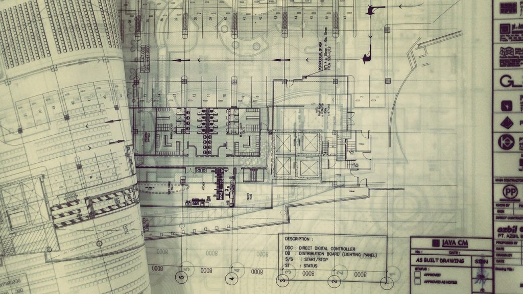
In the world of construction, blueprints are the universal language that transforms design imagination into physical reality. They are the detailed visual guides that tell builders what to construct, how to build it, and what materials to use. From residential homes to skyscrapers, every project starts and ends with one central foundation a comprehensive set of blueprints.
But while blueprints are fundamental to the building process, they can also be intimidating to beginners. Filled with lines, symbols, dimensions, and technical notes, they often appear like a complex code meant only for architects and engineers. However, once you understand how to read and interpret them, blueprints reveal a clear story about how every wall, pipe, wire, and beam fits together in perfect harmony.
In this complete and highly detailed guide, we’ll break down what construction blueprints are, their history, key components, types, and how to read them effectively. Whether you’re a student, an aspiring builder, or a property owner planning your first project, this article will help you gain deep insight into one of the most essential tools in the construction industry.
What Are Construction Blueprints?
Construction blueprints are technical drawings that illustrate every aspect of a building project from its layout and dimensions to the electrical, plumbing, and structural systems. They serve as the instruction manual for construction, guiding everyone involved, including architects, engineers, contractors, and inspectors.
A typical set of blueprints includes floor plans, elevations, sections, details, and schedules each offering a specific view or piece of information about the structure. Together, they ensure that every part of the project aligns with design intent, safety codes, and engineering principles.
The term “blueprint” comes from a historical reproduction method that created white lines on blue paper using a chemical process called cyanotype printing. Although modern construction now uses digital drawings (known as plans or construction documents) instead of literal blueprints, the term remains widely used in the industry.
In essence, a blueprint is the visual and technical DNA of a building the single source of truth that communicates design intent to all trades.
Also read: 7 Best Custom Furniture Companies in Bali
A Brief History of Blueprints
Before the digital era, creating multiple copies of architectural drawings was a major challenge. Hand-drawn plans were often made with pencil and ink on vellum or linen, and duplicating them was time-consuming.
In the mid-19th century, the invention of the blueprint process revolutionized architecture and engineering. The process worked by placing a translucent drawing over a sheet coated with ammonium iron citrate and potassium ferrocyanide, then exposing it to sunlight. The light caused a chemical reaction, turning the exposed areas blue while leaving the lines (blocked by ink) white.
This innovation made it easy to reproduce multiple copies of a design accurately an essential breakthrough for industrial-scale construction.
By the late 20th century, the blueprint process gave way to diazo prints, producing blue lines on white paper, and eventually to digital CAD (Computer-Aided Design) and BIM (Building Information Modeling) drawings.
Today, construction professionals rarely use physical blueprints. Instead, they rely on digital plan sets, which can be viewed, shared, and updated instantly across cloud platforms. Despite this evolution, the core principles of reading and interpreting blueprints remain unchanged.

The Purpose of Blueprints in Construction
Blueprints are more than just drawings — they are the communication backbone of construction projects. Their primary purposes include:
a. Communicating Design Intent
Blueprints translate the architect’s and engineer’s ideas into precise, measurable details that builders can understand and execute.
b. Ensuring Coordination Among Trades
Each trade — from electricians to plumbers — relies on blueprints to understand how their work fits into the bigger picture. For example, electrical plans show where outlets go relative to plumbing fixtures or structural beams.
c. Maintaining Compliance with Building Codes
Blueprints include notes and specifications that ensure compliance with local codes, safety regulations, and zoning laws.
d. Facilitating Cost Estimation and Scheduling
Contractors use blueprints to calculate quantities of materials, estimate labor costs, and develop project schedules.
e. Providing Documentation for Permits and Approvals
Local authorities require detailed drawings for reviewing and approving building permits before construction begins.
f. Guiding Maintenance and Future Modifications
After construction, blueprints serve as a permanent reference for maintenance, renovation, or expansion projects.
Without accurate and detailed blueprints, even the most skilled construction teams would be working blindly.
The Key Components of a Construction Blueprint
A complete set of blueprints is made up of several coordinated sheets, each serving a specific purpose. Let’s break down the essential components.
1. Title Sheet (Cover Page)
This is the first page of the blueprint set. It provides an overview of the project, including:
- Project name and address
- Architect’s and engineer’s information
- Drawing index (list of all sheets)
- Revisions history
- Relevant codes and standards
The title sheet acts as the “table of contents” for the entire document set.
2. Site Plan
A site plan shows the building’s placement on the property relative to roads, boundaries, and other features. It includes details like:
- Property lines and setbacks
- Driveways, walkways, and parking areas
- Drainage systems
- Landscaping and grading
- North arrow for orientation
The site plan ensures that the building fits properly within the legal boundaries and environmental context of the site.
3. Floor Plans
Floor plans are the most familiar type of construction drawing. They represent a horizontal “slice” through the building — typically taken about four feet above the floor — showing the layout of walls, doors, windows, and rooms.
Each floor level has its own plan, with details including:
- Room names and dimensions
- Wall types and thickness
- Door and window symbols
- Stair locations
- Furniture layout (sometimes shown for context)
Floor plans are crucial for both design understanding and actual construction sequencing.
4. Elevations
Elevations are flat views of the building’s exterior or interior walls. They show height, materials, and architectural details.
For example:
- Exterior elevations show façade elements, roof slopes, and exterior finishes.
- Interior elevations are used for bathrooms, kitchens, and other detailed areas.
Elevations help visualize how the final structure will appear and are essential for finishing and material coordination.
5. Sections
A section drawing shows a cut-through of the building to reveal interior construction details not visible in floor plans.
For instance, a wall section may show:
- Wall layers (drywall, insulation, framing)
- Floor and roof connections
- Foundation details
- Ceiling heights
Sections provide a deep understanding of the structural and architectural integration within the building.
6. Details
Detail drawings zoom in on specific components that require additional clarification — such as window jambs, staircases, handrails, or foundation joints.
These small-scale drawings ensure builders understand precisely how components connect and what materials to use.
7. Schedules
Schedules are tables listing repetitive building elements with specifications. Common examples include:
- Door schedule: lists door sizes, types, materials, and hardware.
- Window schedule: includes glazing types, frame materials, and opening styles.
- Finish schedule: specifies floor, wall, and ceiling finishes for each room.
Schedules provide quick, organized reference data that complements the drawings.
8. Structural, Mechanical, Electrical, and Plumbing (MEP) Plans
In addition to architectural drawings, blueprints also include specialized technical sheets:
- Structural Plans: Show beams, columns, footings, and reinforcement details.
- Mechanical Plans: Include HVAC ductwork, ventilation, and equipment placement.
- Electrical Plans: Display power distribution, lighting, outlets, and circuits.
- Plumbing Plans: Show piping routes, fixture locations, and drainage systems.
These MEP plans are coordinated with architectural drawings to avoid conflicts and ensure smooth installation.
9. Specifications (Specs)
Though often separate from the drawings, specifications are an essential companion to blueprints. They describe materials, workmanship standards, and performance criteria in written form.
Together, drawings and specs form the complete Construction Documents (CDs) package.
Understanding Blueprint Symbols and Conventions
Blueprints use a system of standardized symbols and conventions to convey complex information quickly.
Common Blueprint Symbols:
- Walls: Solid or double lines showing wall thickness and type.
- Doors: Arcs indicating swing direction.
- Windows: Parallel lines or rectangles within wall segments.
- Stairs: Series of parallel lines with arrows showing direction (up or down).
- Electrical Outlets: Small circles or icons indicating outlet types.
- Lighting: Symbols for switches, lights, and fixtures.
- Plumbing Fixtures: Icons representing sinks, toilets, showers, etc.
Each blueprint includes a legend or key that explains these symbols. Understanding them is essential for accurate interpretation.
How to Read Construction Blueprints
Reading blueprints is a skill that improves with practice, but a structured approach helps beginners quickly build confidence.
Step 1: Start with the Title Block
The title block (usually found on the right or bottom corner) contains crucial information — drawing title, scale, date, revision number, and designer details.
Step 2: Review the Sheet Index
Use the drawing index on the cover sheet to locate specific plans within the full set.
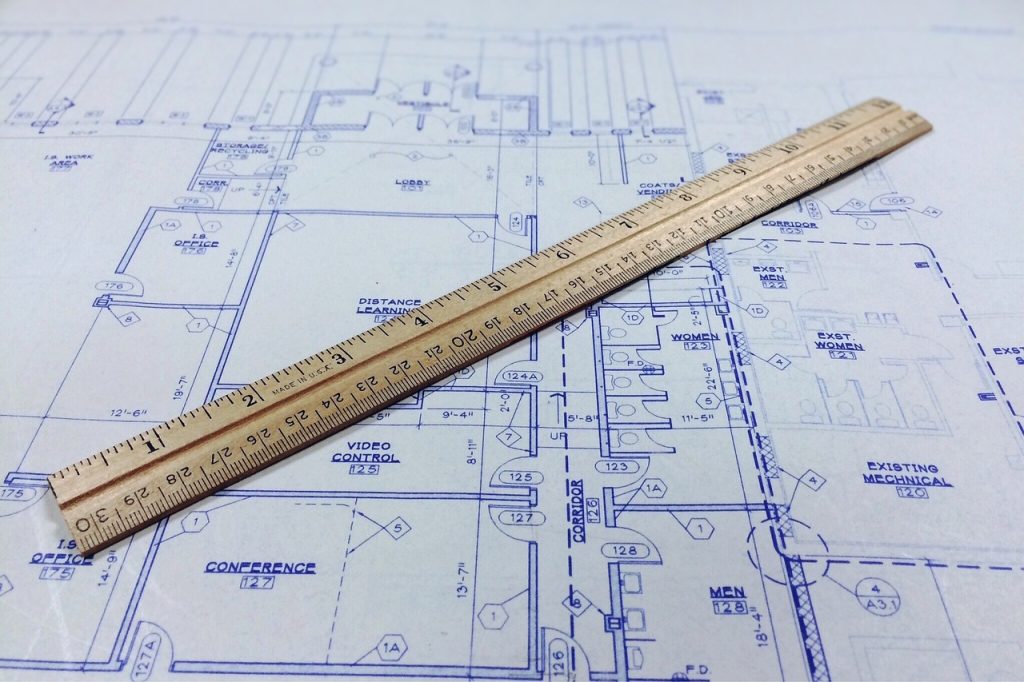
Step 3: Identify Scales
Blueprints are drawn to scale (e.g., 1/4” = 1’-0”). Understanding the scale helps you measure real-world distances accurately using a scale ruler.
Step 4: Study Floor Plans First
Begin with the overall layout to understand spatial relationships, room sizes, and circulation paths.
Step 5: Move to Elevations and Sections
These show how the design looks in three dimensions and how structural and architectural elements align vertically.
Step 6: Review Details and Schedules
Focus on material specifications and component details that clarify how the building elements are assembled.
Step 7: Cross-Reference MEP Drawings
Always check mechanical, electrical, and plumbing plans alongside architectural drawings to ensure consistency.
Step 8: Note Revisions and Markups
Look for revision clouds or symbols indicating updates. The revision schedule lists what changes were made and when.
Once you understand these steps, you’ll be able to read and interpret any professional blueprint confidently.
The Role of Digital Blueprints in Modern Construction
With the advancement of technology, construction blueprints have evolved into dynamic digital tools that offer far more than traditional 2D drawings.
a. CAD (Computer-Aided Design)
Software like AutoCAD replaced manual drafting, enabling precise digital drawings that can be easily edited, scaled, and printed.
b. BIM (Building Information Modeling)
BIM goes beyond 2D plans by creating intelligent 3D models containing data about materials, quantities, and performance. It allows architects, engineers, and contractors to collaborate seamlessly.
c. Cloud-Based Collaboration
Platforms like Autodesk Construction Cloud and Bluebeam Revu allow teams to share, comment, and update blueprints in real time — ensuring everyone works from the latest version.
d. Augmented and Virtual Reality
Some projects now use AR and VR to visualize blueprints in immersive environments, helping clients and builders experience spaces before they’re built.
e. Digital Twins
As-built blueprints can be integrated with sensors to create digital twins — real-time virtual replicas of buildings for monitoring and maintenance.
These innovations mark a shift from static paper drawings to interactive digital ecosystems, improving accuracy, collaboration, and efficiency.
Common Mistakes When Reading Blueprints (and How to Avoid Them)
Even experienced builders sometimes misinterpret blueprints. Here are common pitfalls and how to prevent them:
- Ignoring the Scale – Always check the scale before measuring distances.
- Overlooking Revisions – Use the latest version to avoid outdated data.
- Misreading Symbols – Refer to the legend to confirm meaning.
- Failing to Cross-Check MEP Plans – Overlaps between trades cause costly errors.
- Not Reviewing Details – Small-scale detail drawings often contain critical information.
- Neglecting Specifications – Drawings show “what” to build; specs explain “how” to build it.
Careful, methodical review prevents costly mistakes during construction.
Also read: 7 Best Custom Home Builders to Consider in Bali
Why Blueprint Literacy Is Essential for Every Construction Professional
Blueprint literacy isn’t just for architects — it’s essential for everyone in the construction ecosystem:
- Project Managers use blueprints to plan resources and monitor progress.
- Contractors and Builders follow drawings to execute tasks precisely.
- Inspectors check compliance with codes and design intent.
- Suppliers use them to determine quantities and delivery schedules.
- Clients and Owners use them to visualize the final product and verify project scope.
The ability to read and interpret blueprints accurately enhances collaboration, reduces misunderstandings, and ensures smooth project execution.
Conclusion
Blueprints are far more than lines on paper — they are the language of construction, bridging the gap between design vision and built reality. They ensure that every professional involved in a project speaks the same technical language, minimizing errors and maximizing efficiency.
In today’s digital era, blueprints continue to evolve through technologies like BIM and cloud collaboration, but their core purpose remains unchanged: to communicate design intent clearly and precisely.
For beginners entering the construction field, learning how to read blueprints is one of the most powerful skills you can develop. It opens the door to understanding how ideas transform into structures that shape our cities and communities.
Mastering blueprints means mastering the art of building itself — an essential step toward becoming a true professional in the world of construction.


Gracia Rena
Gracia is a co-owner of the company and a seasoned professional with over 20 years of experience in the hospitality industry. Her impressive background includes roles at major organizations such as Marriott, Accor, Banyan Tree, Sudamala, and Singapore Airlines.
With a profound understanding of luxury service standards and operational excellence, Gracia brings invaluable expertise to the business. Her strategic insight and dedication to quality have been instrumental in shaping the company’s growth, ensuring its continued reputation for delivering exceptional value and innovation in hospitality and commercial projects across the region.